All about Tubes, Tube Circuits, Tube Gear

Monday, June 25, 2012

RIAA Preamp (part 6):

Here are the last useful RIAA EQs:


(G) Columbia 78 rpm


 (F) RCA 78 rpm

(H):  Decca FFRR
 

 Note that with the last (Decca FFRR), only the lower left cap is the same, and this is best made up as a separate network.


Sunday, June 24, 2012

RIAA Preamp Build (part 5): Extras

Now lets take the basic RIAA (Flat Xover),
and form two more of the most popular EQs:

(D)  The NARTB Standard:  (Artist, Capitol, M.G.M., and many other American pressings) = (C) The 500 Hz Flat Xover + a cap:


and finally,

(E)  The Columbia Microgroove:  (NARTB + a resistor):

We can also squeeze out the RCA Victor 78 rpm EQ from a basic RIAA (flat 500), by adding an additional L-network, but after this we have to start from scratch to punch out the last two, (Decca FFRR, and Columbia 78 std.), because they require more extensive changes.

Well, it shouldn't take much imagination to wire up a switch or two to eek out at least 5 RIAA EQ settings.

RIAA Preamp Build (part 4): 2-stage standard

Lets look at a basic 2-stage RIAA preamp from the early 50s.


As expected, the RIAA EQ will be inserted after the first stage, where headroom can be found and behavior controlled.

There are actually two parts to the circuit in regards to phono cartridges.

(1)  The Input Impedance of the Unit. (R in).  This will be set to 16K for ceramic cartridges, and otherwise, for magnetic cartridges, it should match that specified by the maker of the cartridge.  Thus you could have a couple of resistors here to switch in and out depending upon the cartridge you were using, or a Ceramic/Magnetic setting.

(2)  The RIAA Network Proper.  This is a 3-terminal (in/out/ground) interchangeable or adjustable network, activated by selection switches.   Note the pre-specified .0068 uF input cap, and the 1 Meg output load to the next stage.  These are chosen as a base for the variations to follow.


Circuit Operation:

The 6SL7 is chosen for its high Mu (gain).  With all high Mu triodes, care should be taken to prevent HF rolloff from Miller capacitance.  Here with a gain of 30 and a MC in the order of 100 uuFd, the output Z of the source shouldn't be higher than 75K to keep the 3db point above 20kHz.  Luckily both ceramics and magnetics generally have Out Z lower than this.

We now design the Out Z of the RIAA circuit etc. to keep the signal to stage 2 low in size (and distortion).   The EQ circuit will have an Amplification factor of .022 at 1kHz, even at 20 Hz the Amplificatoin (after losses) will be only about .33.  This means you can have a bias as low as -2 volts on the 2nd stage, and a typical input signal of .1 volt to the first stage.

1K R Cathode resistors will typically be bypassed with a 47 uF cap to keep up the gain and most importantly to reduce heater hum.   To keep the signal clean, this (electrolytic) can itself be bypassed with a small polypropolene for signal clarity, slew-rate and reduced noise.

In these low-signal circuits you need a really good, well filtered Power Supply.  In my view this makes the Mu-Follower the ideal method for supplying the HV.


Design of the RIAA Circuit (EQ):

(1)  First, the input Z which the first stage sees must be high enough not to load the tube too much, (which would cause distortion).

(2)  Second, the Out Z presented to the 2nd stage should be low enough not to lose high end through Miller Capacitance. 

(3)  Finally, if you have more than one RIAA circuit, they should be matched in overall attenuation losses so you can switch easily between settings without volume problems.

Flat Turnover EQ:

A basic L-circuit does the trick for flat recordings with a fixed turn-over point (i.e., where the gain is about 0 db).

(A) 250 Hz Flat Xover:  For British H.M.V. and other European pressings (Mittell, B.E.B., etc)

(B)  500 Hz Flat Xover:  Older American Vintage pressings.

(C)  1 kHz  Flat Xover:  Some rare European recordings.


RIAA Preamp Build (part 3)


RIAA circuits 101

We could get into an extended discussion of RIAA equalization and its history, but why bother?  This would be overkill for the average DIYer.

All we really need is the basic overview, and some idea of how to successfully integrate standard and practical circuits into our preamp.  No point in re-inventing the wheel.

So lets skip the worst of the technical questions and complex equations for filter networks, and look at some real-world examples, which we can modify for our purposes.

First of all, the overview:

It is generally best to either do the EQing after the first stage of amplification, or between two stages in the signal path, so we can gain the headroom needed and control the results of our efforts.


Since we will probably only have a single stage, our RIAA network will come afterward, once the signal is amplified.

RIAA Preamp Build (part 2)

Mu-follower circuits have been well discussed, ... so I will leave the basic circuit to one side for now, and discuss RIAA.

We may note in passing that in the evolution of music recording, various media and techniques were developed, each with its own problems, side-effects and equalization requirements.

The main problem with recording was the limitation and the skewedness of the frequency response.

An ideal frequency response would be similar to that claimed for a modern stereo amp:

Click the image to open in full size.

However, the actual process of recording would imprint its own frequency response 'fingerprint' or bias. Thus a magnetic phono record response curve might look more like this:

Click the image to open in full size.

That is, in the process of recording, the final product (a vinyl record and playback needle) has very loud treble, and very little bass.

As a result, the signal needs heavy correction or 'equalization' to restore the sound back to how it originally sounded. Thus the "equalizer" was originally a correction device in the playback chain to compensate for frequency response distortion in the recording and playback media chain.

The "Equalization" is imposed in the preamp stage, just after the signal is retrieved from the record through the magnetic cartridge. Like an adjustable tone control, this circuit imposes its own curve on the signal:

Click the image to open in full size.

The two filtering processes (recording and playback) are supposed to cancel each other out, restoring the signal to its original balance, and achieving a more or less flat frequency response overall.

As a matter of history, early attempts at equalization had some variations, before some semblance of standardization sorted itself out in the marketplace, and in the interim, several hi-fi equipment makers offered alternate settings to more closely accommodate various recordings the methods used. The McIntosh AE-2 (pre)amplifier Equalizer control (1950) for instance offered both a 5-position switch and bass and treble adjustments:

Click the image to open in full size.


Today, an RIAA equalization circuit is usually a simplified version (a compromise) of the various EQ curves and standards floating about in the 50s and 60s. It is assumed that most stereo systems will have some kind of 'fine tuning' tone-control adjustments, so that specialized RIAA circuits for each case are not really needed.

Those who are serious about playing back their vinyl records as they were really intended, and with the best fidelity however, will not be satisfied with such commercial compromises, and will want to have a selection of RIAA equalization circuits at hand for playing various records.

In terms of the variations, the following main cases are:

(1) the Columbia 78 rpm circuit

(2) the Columbia 33.3

(3) the RCA Victor 78 and 45 rpm,

(4) the RCA Victor 33.3, and Concert Hall 78 versions.

(4) the London (records) FFRR and Decca FFRR.

These are the most used and most popular versions.

If you have a swelling vinyl collection, it might be wise to do some sorting or labeling on the basis of the RIAA type or equalization needed.
The brand-names and dating will go a long way toward sorting out the issues.

Saturday, June 23, 2012

Marshall Cab (3)

Just an update:
I installed the 2 12" Pro Blue bass drivers,
and tried hooking up just one:
Wow!  So that is what good loud bass sounds like!


Friday, June 22, 2012

RIAA Preamp Build (Part 1)

Well, someone asked me to design a low-noise stereo preamp for RIAA, (record phono input Equalization), so Challenge Accepted!

I made a preliminary design effort using a Mu-Follower type layout for dead-quiet PSRR and low noise, and also chose a low-voltage tube.  I will be using either 6922s or a 6GM8.

Decided on separate power supply and preamp chassis, for even lower noise, because this is a really low-voltage input signal (old magnetic cartridges etc.).

I enlisted the boy to help me with the power supply.  I took a standard but nice-looking metal box as a base.

The boy loves these special wire-strippers.  He thinks they look like Oscar the Grouch, and calls them the "Eyebrow tool":


I happened to have a ready-made 60 volt filtered supply PCB, loaded and tested. All that was needed was a 12 vAC transformer.  Well, I ordered one on Ebay (notice it says right on it TRANSFORMER).  I assumed the housing was just shielding and a convenient mounting.  This turned out not to be a transformer at all, but a DC power supply containing a transformer!  Who knew!  Idiots.


Well, pressing on, I got some four-wire shielded cable and attached a nice solid connector to it.  This will go to the preamp chassis proper.   I improved the HV insulation inside the plug by weaving electrical tape between the pins.


For tagging purposes, (and additional isolation), I re-paired (no pun) the wires so that the heater (which doesn't matter is two whites, and the HV (60v) is blue/orange (-/+).  Keeps things simple to hook up correctly.


Here's a sneak preview of the other half of the project: My part collection for the preamp itself.  I'm using this nice knick knack box as a base, it looks really nice.  It will have two tubes on it, and some RCA jacks, and a pwr connector.


Not a lot to remark on schematic-wise so far.  Will discuss circuits in following posts.

Wednesday, June 20, 2012

Fender Rumble 60 Upgrade


I just inherited this Rumble 60, and I note it seems to have an 8 ohm Fender Special musical instrument speaker.  However, this speaker is actually undersize compared to a regular Fender 12", and seems to be only about a 40 watt speaker.

Note the small magnet.


The cabinet could use reinforcing,
and it looks like I could reinforce corners/edges inside,
seal the box and port too:


Bass Reflex Cabinet w. slot along bottom:


9" deep X 15 3/8" wide x 15 1/4" high (16 3/4" at back) interior box,

= 2140 cubic inches (1.24 ft³, .035 m³ )

with port/slot = 3/4" high x 16" wide, (12 Sq. In.)
and about 7" deep. (84 cubic in. in volume).


On the other hand,
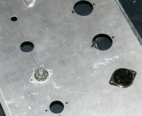
The chassis for the Rumble 60 (at least this one) isn't made of Aluminium! It seems to be soft steel.

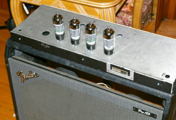
Its solid, rectangular and just about perfect for a small 2-tube push-pull power section.

I'd have to build a separate wood cabinet for it (Marshall-style).

Click the image to open in full size.

Somebody maybe already got that idea, and sold a chassis on Ebay.

I'm thinking, - now that the Rumble 60 has been discontinued,
and it has gone down from $500 new to about $200 or less used,
it makes a good start-pack for a 'champ' project complete with speaker cabinet!.

I don't know if this speaker would satisfy a guitarist,
but the chassis should satisfy a DIYer!

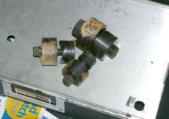
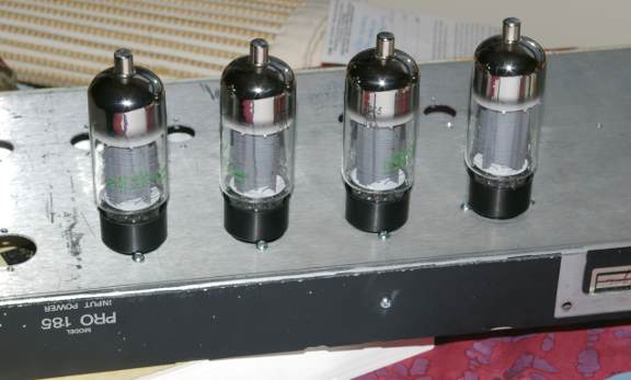
 Okay here's a closer look:

Click the image to open in full size.

16.5 " wide x 9.75 " deep x 2.75 " (at back. 2.25" front) chassis


______________________________

Recommendations for Amp:

Chuck integrated chip-amp,
and build tube amp on chassis, mount it in separate Marshall-style box.

Ok so the chassis is 16.5" wide (without any sides),
and 10" deep (ignoring transformer bulge and knobs).

I'm guessing a separate 'head' box will be:

(inside: 16.75" x 12" deep (allow for knobs/fuses) x 8" (3" + at least 5"))

Add 3/4" ply (x2) box:

18.25" x 12 (or 13)" deep by 10" high.
You can use the metal speaker-grill (cut) as a front/back grid above the chassis / knobs, to keep fingers out of front and back, and have plywood top, bottom and sides.
Carpet (or woodfinish) and corners as desired.

Makes for a sweet looking 60w push-pull head.


------------------------------

Recommendations for Speaker Cabinet:
 
As it is, the cabinet has a horrible "honk/peak" on the low E string (G,G#),
and another one about an octave higher (Gb, G, G# smeared).

Its a very uneven bass response, almost unplayable in certain areas of the fretboard!

The four-knob EQ doesn't fix this,- not even in the ballpark.


I'm thinking: put a real 200 watt speaker in it,
seal the port with a plywood block,
maybe add a midrange speaker (in separate compartment) + crossover.

Reinforce cabinet walls with crossbraces,
and foam 3 sides inside to stop standing reflections.

 To update:


I've added wheels (a necessity with any amp larger than a 10watt).

Also:

I reinforced the inside with a cross-piece horizontal pine board about 1" thick and 4" wide, edgewise toward speaker-back, cutting back-panel in half. Screws in sides and back and glue to hold.

I added a 16" piece of 2x4 in bottom, after removing fruity lightshow panel, right on bottom and right against port-hole inside blocking it: glued and screwed from bottom/sides (1.5" screws).
Long-screws were used on ends (from side).

I used a spray-can of insulating-foam, filling port, corners and edges all around inside box. Worked well.

I replaced speaker and tested:

The two main resonances were still there, (49 Hz and 98 Hz), but a little less bad. Much of the cabinent distortion on other notes however were cleaned up, so this cabinet reinforcement is really worth doing.

I went back to my buddy at The Speaker Store, asked about a notch-filter. This was not good news, as the cap/inductor combo would require 150 mH (HUGE if aircore) and 20,000 - 40,000 uF caps. The cost was unjustifiable, and the coil was made of unobtainium.

But the good news is my speaker expert recommended
stuffing the cabinet full of quilt-stuffing material to kill all standing waves.
So I gutted a 'comforter/pillow' and stuffed cabinet and replaced speaker:


...FANTASTIC!
The two main resonances were about 80% killed off (still a slight and noticable peak/resonance but the bass guitar was actually playable and the notes near the 'resonance' weren't all blended together and indistinguishable.

Also, the whole bass fretboard was not only playable but sounded musically awesome (especially two-note stuff and octaves)!

Bass Guitar amp went from pure honky crap to sonic bliss.

Pull all your bass woofers, reinforce sides and stuff the box full!
You will be amazed.

Now the amp actually doesn't sound so bad (for a transistor),
although the EQ is still crap.

In an ordinary room (practice, coffeeshops) it seems more than adequate.
Also seems to work good as a small guitar amp (maybe better than as a bass).

Still, speaker seems underpower for useful playing.

I'm now thinking of just adding a tube-circuit (12ax7 etc.) inside the box for an 'overdrive' channel:
You don't have to make a separate 'head' for this, to get a 'tube' sound.

I will get back again on this.

 "you mean, you sealed that .75" gap on the bottom of front?
isn't that needed to let the pressure out, so speaker won't blow up? "

Yes I blocked that, to get a smoother frequency response.


No, unless you are pumping ridiculous levels of power into it.

The sealed cabinet should limit the excursion somewhat,
protecting the speaker against physical overload.

I think there is some problems with paper-accordion surrounds (i.e., guitar speakers) handling extreme excursions of bass,
and supposedly the surrounds can tear.
It may be that this speaker (the original equipment) is susceptable to this, if pushed:
It certainly looks rather underrated (small magnet etc.) for a bass speaker.
But I think Fender would have put a speaker in that can handle bass,
since they contract speaker-makers to customize their speaker requirements.

I haven't overdriven it, but no one should with a small cab/speaker like this. Its strictly for practice and coffee-shops.

I was tempted to drop in a guitar-speaker (higher power) but resisted the temptation, since guitar-speakers are not made for bass-excursion.

I am still tempted to further modify the cab:

That is, put a Karlson-skirt on it to greatly amplify the loudness for a given wattage. If this was done properly,
the amp/speaker combo could probably power a rock-band / bar scene.

Tuesday, June 19, 2012

Woofer Distortion 101


Recently there was a discussion in regard to speaker distortion.  It was about what happens when you have two woofers in one box, but have them crossed-over at different points.

A poster wasn't able to articulate his point, and as a result of some confusing expressions, left people thinking he was 'trolling'.

In fact, he was right on the essential point, which I'm going to illustrate with some diagrams here:

Diagram 1:  Two Separate Cabinets vs. One Cabinet


What actually happens when two woofers share the same cabinet?
Well, in the above diagram, there isn't much difference between the two situations.   If this isn't clear, the following diagram should help out:

Diagram 2:  Front and Back Radiation

Above we assume that both speakers are wired "in phase", which means that regardless of whether they are in series or in parallel, the coils are set so that a positive voltage across the marked terminals makes both speakers move outward, while a negative voltage makes the speakers move in.  You can test this with a small battery.

The sound waves are pushed simultaneously in the same direction out the front, and they make a large parallel wavefront, twice as powerful as either speaker alone.   In the back, a sound wave of opposite phase is pressed against every wall of the inside of the cabinet, with only a short delay from the speaker to the cabinet-wall.

By inspection, we may note that the sound pressure is applied equally to both sides of the separating wall in the first cabinet.  When the speakers are moving out, they create suction inside, and when the speakers are sucking inward, they increase pressure in the cabinet.   That is, while the action inside the cabinet is the opposite of that outside,  the same thing happens in both compartments at the same time, either high pressure in both, or low pressure.

 This means that the pressure is equal on both sides of the separating wall at all times, and according to classical mechanics, there is then no net-force on the separating panel, and no energy will be exchanged between the two partitions.   From this it should make no difference if the wall is removed, as in the speaker cabinet on the right.  The forces (both pressure and vacuum) are equal and opposite, and cancel inside the box.


 Distortion from Excursion

Another thing to observe, is that the loudness of a sound of a given frequency will be based on how much air is pushed, or the area of the woofer surface.  It follows that doubling the number of speakers will give us one of two options.

(1)  If the two speakers are in parallel, and are presented with the same voltage (speakers are voltage-operated devices), we will have twice the air and twice the power used, which means a lot more loudness.

(2)  Alternately, and this is much more interesting, we can instead put half the power into each speaker, and get the same volume, with each speaker doing half the work.  So what?  Well, it means that each speaker only needs to physically move half as much, for the pair to move the same amount of air.

Why is (2) significant?  If speakers move too much, the result is distortion.   Speakers have a limited excursion, that is, they can only move so much before they put up too much resistance, and start either clipping the signal, or they might get out of control.    The excursion is a measure of headroom, or freedom to respond to signals.  If the speaker is already playing a loud bass-note for instance, and is moving at its maximum swing, it can't respond when another musical note is added on top.  There is no more headroom, and the new signal is either attenuated, or otherwise distorted.  This can be referred to as Intermodulation (or I.M.) distortion, and happens at higher volumes as the speaker puts up more resistance and changes the wave-shape, which automatically adds harmonics or sidebands, and attenuates other frequencies.

Splitting the bass-load between two speakers will then cut back a large amount of distortion, and leave headroom for more  musical input, with much less I.M. distortion.   Of course this is very similar to simply using a larger speaker, which can then output more bass with less motion, and less distortion.

Thus many people might presume that this can only be a good thing, and that there is no trade-off in musical quality by doubling the speakers (other than cost!).  We will see if that is always the case, below.


All this is just the necessary background to the discussion at hand, which originally took place on the DIYaudio forum. 

Here is the link, although some of the discussion may have been subsequently deleted.

3.5 way speaker design, should I put the woofers together?

 ----------------------------------------------
In the original discussion, the speaker builder wanted to have two speakers, but with only one speaker  carrying some midrange also.  This is done simply by having a different crossover-point for each woofer.  One speaker would just carry the bass, while the other would carry both bass and lower mids.

The argument was as to whether or not there was a musical drawback to the method of doubling the woofer, operating the two woofers across different bandwidths, while having them share the same box.

The poster felt that there would be distortion because of this, and he was essentially right. 

Diagram 3:  Midrange Bleed-Through
Lets assume the top speaker is the one that will carry the extra midrange musical content.  In the separate compartments, the out-of-phase back-wave from the speaker would mostly be absorbed by the box, and only a small amount would feedback to the originating speaker, resisting and affecting the signal radiating out the front.

Now look at the diagram on the right:

Without the barrier, the back-wave from the top speaker will also reach the bottom speaker, and radiate out through the cone.  From the point of view of the cone, it matters not whether the signal is imposed upon it from an electrical signal via the coil, or mechanically from the back via the air.  The cone will move (vibrate), and the sound will radiate out.  The cone is a relatively thin and pervious veil over the lower hole, and permits sound to escape the box.


The Flange-Effect

However, this new copy of the midrange signal is not identical to the original.  It has now been time-delayed, much as the sound from a port is.  Here however, the midrange sounds are very short wavelengths, and will alternately cancel and reinforce the original signal, depending upon wavelength.  This acts as a fixed-frequency comb-filter, as well as a phase-shifting filter.

Compounding this comb-filter/delay flanging effect will be the secondary I.M. distortion added by the moving lower speaker, pumping bass.  Almost the same amount of I.M. distortion being added to the midrange already via the top speaker will also be added to the inverted signal radiating out the bottom.

Diagram 4: Intermodulation Distortion


This does not negate the gains achieved by doubling the bass-woofer.  But now the midrange being reproduced by the system is accumulating distortion of an entirely different kind than would have originally been the case for a single driver with no radiator or port.  And it should be remembered that the same gains in lowering I.M. distortion could have been achieved with a single larger woofer.

Thus two questions need to be asked: 

(1)  Why would you choose to have two smaller woofers rather than one larger one?   The answer ought to be, that some other benefit is achieved, namely a different frequency response, or cabinet resonance, or speaker specs, which would move the builder to take on the extra work of designing for two speakers.

(2)  Secondly, can anything be done to minimize the drawbacks introduced by two speakers in one cabinet?   Well, the answer is a definite yes!  The simple act of dividing the cabinet into two compartments, and stuffing the top with absorbent materials, should eliminate the undesirable 'flanging effect' we can expect from single compartment.

Thus, that poster was right when he insisted that the design could be significantly improved by partitioning the cabinet.


Monday, June 18, 2012

Ultralinear Guitar Amp (10): Transformers, Grommet!


Transformers, Grommet!


 Yes, whenever you mount transformers to a chassis, always have plenty of rubber grommets to protect the wiring insulation from abrasion, cuts, and short-circuiting!  Especially with high voltage stuff.


First Transformer goes on the Chassis!  Output tranny at one end, and power supply trannies and chokes at the other.  Orientation aint so critical with this incredibly long chassis.


 I always seem to be short of lock-washers.  Ideally locknuts would be even better, but hey, we'll be using what is on hand for this economy build.  When you run out of washers, you can always use nail-polish to fix nuts from loosening, that are never supposed to come off again.  Transformers are one of those parts that should never die!


The second (Power/HV) Tranny goes in the corner.
Here my son is drilling the holes for the massive choke (larger than the Power Tranny!).  We had to check for clearance with the speakers in the Fender cab.


After this quick training exercise, my son is now a professional Grommeter!
It first seems impossible to stuff correct-size grommets into the hole, And in the past I've even cut them to assist in tucking them in.  But the best tool for this is simply a medium flat-head screwdriver.  You have to watch it, so that the rubber isn't penetrated or torn, since that defeats the whole (hole) purpose of protecting the wires from contact with sharp metal edges, and also providing electrical insulation.


Power Plug Innovations:

Next we want to get the power chord installed.  But here, instead of the usual fixed line, we want the new 'computer-plug' style.  There are several good reasons to go this route:

(1)  If the chord is damaged, its an easy replacement, without tools!

(2)  You can change the length of the power cord, if you want to add a longer one!

(3)  There is built-in powerline filtering in most of these units, which is pretty essential these days with tons of digital broadcast noise all around, (cells, internet etc.) and all kinds of equipment piggy-backing on powerlines (local transmission of security, LANS, even audio!).


 But alas, there's a snag!  How do you cut a square/rectangular hole with ordinary tools?  Sure, of course you can make four or more holes with your drill, dig out the jigsaw and cut out the extra metal, and finish up with some various sized metal files; all a lot of annoying and boring work, which is also time-consuming.

Or you can graduate to

The Nibbler!

When I found out about this tool, I fell in love!   It does just what they call it, It nibbles out sheetmetal of almost any thickness or type, and its easy and fast.
Of course the metal handle isn't the most comfortable, but you can either wear a glove, tape on some rubber padding or apply insulating sheaths from a pair of pliers, or just MAN UP and cut the hole!  Usually for one or two holes, you don't need to do much except mark out the size and nibble away!


To get started, you just drill a 3/8" or larger pilot hole to work the tool in to where it can start chopping.  Be sure to use cutting oil to protect the sharpness of your Nibbler tool, which is going to become your favorite tool for cutting perfect rectangular shapes, refitting new parts which are the wrong size, etc.


Here the son gets an instructional hands-on in Nibbling 101.   Soon the AC socket will be ready for power!


A final nostalgic look at today's accomplishments.  Time to rest.
I don't want to tucker the boy out.


A few more internals, like caps, a bridge and a power-switch and fuse, and we'll be ready to wire up and test the output stage!

For that, all we need is a good tube-pedal (like one we built earlier) to drive the splitter, Output stage and transformer!   Lets rock!


Thursday, June 14, 2012

Ultralinear Guitar Amp (9): Tube Holes!


Starting to prep the Chassis!

Here's the latest pics of the build:


These hole-punches are a lifesaver.
They pay for themselves with their first use.
Make sure you use cutting-oil and regular oil on the threads, to keep them sharp.


For accurate hole-placement, small pilot-holes are drilled, then a 3/8" hole for the bolt of the hole-punch.
A half-dozen turns and the piece snaps out, leaving a perfect, finished hole.


Even if this project is a flop, nothing beats watching the son actually perform useful work!
- and he's gained experience with a new tool, the hole-punch.


Holes for the mounting bolts are also marked and drilled.


Really nothing should be mounted until the transformers are drilled and bolted on,
but its hard to resist the fun of pre-assembly and a first look:


Ultralinear Guitar Amp (8): Chassis Prep (cont.)

Nothing like actually getting down to business!

The chassis needed one more modification.
The extra long back was sawed off, leaving about an inch;


The extra piece was also sawed short, to match the height;

This piece has the bend and chassis-bolt nuts which take the back bolts from above.


The piece is bolted to the rest of the chassis, to give a strong,
level surface for mounting the transformers and tubes.

As a result, new holes will have to be drilled in sides of the wooden Fender cab, to line up with the side-bolts.

Good news is, most of the front panel can be re-used, the old way,
with chassis-mounted knobs and point-to-point, using a turret board.


Here's a closeup of the Boltec 100watt UL transformer, with painted bells.
The 'burnt look' was created with a crackle-paint, sprayed lightly over the white.
It gives a hint of the mayhem to come from this best guitar-amp ever built (tribute).


Now the fun begins! LAYOUT Time!


Nothing like a new amp project to get you all fired up!

Click the image to open in full size.

Remember kids! Play Safe!

Click the image to open in full size.