(a) Grid Stoppers: (1.5k - 5.6k ohm
range?) I'd like advice on these, I'm not worried about losing a bit
of signal, but would rather have stability and immunity from RF...
Reading over the thread on tube tracer building, I was impressed by the fact that even in what seems like simple stable circuits, tubes were still prone to oscillation and excitation, so much so that relatively frequently the tube tester lads were adding resistors to prevent it. This seems to underline the idea that Grid Stoppers are not merely 'just in case' options, but necessary circuit elements. Especially when later users are likely to experiment with substituted tubes, a choice of grid stopper that allows the amp to behave under a variety of conditions seems like a good design goal. In my mind, one can't solve every possible event, but if I limit the list of possible output tubes down to a reasonable subset for this topology and voltage range, I get this: (1) 6BG6 (first choice). (2) 6L6GC (2nd choice). (3) EL34 (not a preference, but a likely experiment to beware of) (4) 5881 (this is where it gets iffy, because of lower voltage ratings). I think I may place a sticker inside warning future users not to try lower voltage "6L6"s or 6V6s. But the EL34 should actually work, PROVIDING I prevent too much screen current from flowing. So here is a case where even though I don't like EL34s, it would be smart to design with their possible use in mind. In the case of the 5881s, switching in some kind of B+ voltage drop option might be workable (a "5881" switch of some kind). I think I might need some help on that idea, but it can wait. Now, the grid stopper choice doesn't seem to be too critical, although one thing comes to mind: Even a low value grid stopper might start eating up driver-voltage if there is grid current happening when the amp is pushed. So it looks like the choice should be as low a value as possible, given the range of tubes contemplated. What IS critical here then, is to choose a value that doesn't choke off driver voltage to the grids, while still effectively preventing RF/oscillation and instability. The first thing I am looking at is what other people have done. MARSHALL: I don't think early Marshalls were well-designed, and even though they may have some 'vintage' sound, I don't think their choice of grid-stoppers will be particularly credible. Nonetheless, the JCM800s, which use EL34s (6CA7), all have 1.5k grid stoppers. FENDER: Here I think there might be something to note. I see in the Fender Twin 100w that for 5881s they apparently shared 1.5k grid stoppers (one for two tubes on each side = 750 ohms/tube? ). Still that is not the tube of choice. TRAYNOR: This Canadian amp co. presents some unusually conservative and reliable designs, so its worth looking at. On the 1966 YVM1 Voicemaster they added 10K grid stoppers for 7027 tubes (although many people seem to have substituted EL34s in these old Traynors). This seems unusually high... The YBA1A Bass-Master Mk2 (1971) has added 1.5k grid stoppers, probably following FENDER designs, and accommodating USA-made 6CA7s (high power EL34s). Still, some designs leave out grid-stoppers entirely, right up to 1970 revisions, such as the YBA-3 Custom (4x 6CA7s). HIWATT: Seem to have put original thought/experiment into grid stoppers; they have 22k grid stoppers in their 4xEL34 output stage (200w). MESABOOGIE: they use 220 ohm grid stoppers on their Musicman GP-3, with (EL34?)6CA7s, but they are also using opamp drivers.... Their 1972 OrangeAmp MkII however uses 2.4k grid-stoppers on 4xEL34s. The VOX AC-100 again deviates, with 47k grid-stoppers on only two of the 4 EL34s (not shared!). Looks like some plagarism in design, perhaps following tube-maker guidelines rather blindly, accompanied by a few maverick experiments, but little consistency or clarity in design constraints... Anybody have any experience in this aspect of design? The high values may not be good design choices, (stability problems may be better solved with different methods) , and other variants may be to save on parts, rather than provide 'best design' examples. If part of the goal was to limit grid current in class AB/B modes, there might be more effective ways of doing that without sacrificing driver voltage. ------------------------- Alvis: "OK, then pick your tube, calculate the resistor based on your specific tubes miller effect. General questions get general answers. Weather or not the RF cutoff is at 15Khz or 20Khz is a matter of semantics, both filter out the RF and let the highest guitar frequencies through, hence the range of resistors. Sometimes its nice to have elbow room, a "range" might allow for different tubes types while still doing the job. The effect on audio attenuation is very minimal. Grid Stopper Resistor Calculator Blocking Distortion ---------------------------------- Just for contrast, it might be good to look at a few older solid designs: The Western Electric Model 142A (6L6s) uses only a 100 ohm grid stopper! Such classic designers tended to deal with parasitic RF directly using other methods, rather than choke out driver voltages. On the other hand, one RCA design (mi9377) sports 47k grid stoppers on a 4x 6L6-G design (lower voltages). This seems rather large, especially when we also see regulated screens and RC networks on both halves of the output xformer primary. Looks like a lot of effort went into bullet-proofing this design, but maybe a better layout would have accomplished more! The Natural Horizon 20 uses a mere 470 ohms per 6L6G tube in a 30 watt design. Someone felt it necessary to place 5 ohm resistors on the cathodes of a dual 807 design (high power version of a 6L6). We see a relatively high value (22k) in Bogen's DO-30A (KT66 pentode mode) The model A-30 Circlotron gets by with 120 ohm grid stoppers, on its 6BG6Gs. A 2005 design by Wes Kinsier doesn't use any at all, apparently with good results... An Ultralinear design from the 1990s using 6CA7s uses only 100 ohms of grid-stopper (and a 10 ohm common cathode as per Hafler's recommendations). DuKane's 1A475C (100w) with 4x 6CD6GAs uses 10k grid-stoppers only on the second pair. The "Lil Tiger" mod by Forrest Cook stuffs in 1k grid stoppers on its 6BQ5s. The Altec Lansing A-340A (2x 6550s) also skips them entirely, preferring instead to invest in a regulated screen supply and a multistage FB loop. The Maestro (1951) has none on its 6145 outputs. Gotham's PFB-150WA avoids grid stoppers in its 811A triode design. No grid-stoppers are to be seen in Altec Lansing's 1570B, which sports a pair of 811As. Yet another RCA (MI-12246) has none on its 811As. The Altec Lansing 260A uses only 100 ohm grid stoppers on a pair of 813s, with a thousand watts and dangerously high voltages. As a trend, older amps have lower value grid stoppers, or none at all. Is this development an evolution to compensate for an RF polluted environment? |
|

|
Thursday, June 14, 2012
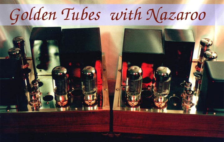
Ultralinear Guitar Amp (2): Grid Stoppers
Subscribe to:
Post Comments (Atom)
No comments:
Post a Comment